
VibroRegen: Harvesting Energy from Vehicle Suspension
Background and Motivation
Something that had been sitting in the back of my mind for a while was the range anxiety problem with EVs. It's one of the most persistent reasons people don't make the switch, and a lot of the discourse around it focuses on bigger batteries or faster charging. What interested me more was whether there was energy already being wasted in the vehicle that could be recovered passively, without adding any active system or extra fuel consumption.
Vehicle suspension systems dissipate somewhere between 80 and 400 watts as heat on a typical passenger car, and up to a kilowatt in heavy goods vehicles. That energy is lost with every bump and undulation in the road, regardless of how the vehicle is being driven. BMW research has suggested that a 300W suspension recovery system could improve fuel efficiency by around 3%, and Audi engineers projected a CO2 reduction of 3g/km and a fuel economy improvement of 0.7L/100km for hybrid applications. The numbers are modest, but the energy is essentially free: it comes from motion that is happening regardless, and it would otherwise do nothing useful.
VibroRegen was my attempt to investigate whether piezoelectric materials, embedded in a car's suspension system, could practically capture some of that energy and convert it into usable electrical power.
Self-Proposing the Project
ES327 at Warwick works by releasing a large list of project options, enough for every student to take one, and students choose from that list. I wanted to work on something in the automotive and EV space, and what I had in mind wasn't on the list, so I asked whether I could propose my own project. It went through a departmental review process and had to be formally approved before it was greenlit.
What that meant in practice was that from the very first day, there was no template or prescribed structure to work within. I had to define the scope myself, work out what was worth investigating and what wasn't, set my own milestones, and hold myself to deadlines I'd written. Over seven months from September through to late March, that involved going through a full literature review, building and iterating a MATLAB/Simulink simulation, designing and building four physical prototype iterations, running a structured test programme, and writing the final report. It was the largest single project I'd taken on, and the most independently managed. The learning curve across all of it was steep, but I thought it went well.
Choosing Piezoelectric Transduction
Three transduction methods were evaluated for converting suspension motion into electricity: electrostatic, electromagnetic, and piezoelectric.
Electrostatic systems require an external voltage source to operate, which makes them unsuitable for a self-sustaining energy harvester from the outset, adding complexity with cable routing and a barrier to implementation. Electromagnetic systems can produce higher absolute power output, but they carry significant mass and volume requirements that conflict with the weight optimisation goals of automotive design. Piezoelectric materials convert mechanical stress directly into electrical charge without needing any external power, offer around three times the energy density of either alternative, and are compact enough to integrate passively alongside existing suspension components.
The material selected was PZT (lead zirconate titanate), with properties targeting a midpoint between the PZT-4 and PZT-8 grades. PZT-5H has a higher piezoelectric coefficient on paper, but its Curie temperature of 193°C and poor mechanical quality factor make it unsuitable for the sustained cyclic loading and temperature variation of a vehicle in real use. PZT-4 and PZT-8 offer better mechanical durability and handle higher temperatures, which is more appropriate for an automotive application. The specific component used was the TDK PowerHap B54102H1020A001, chosen for its performance-to-cost ratio within the project budget. Four elements were configured in parallel rather than series, based on referenced research showing parallel arrangements producing 7.676mW compared to 1.671mW for series under equivalent conditions.
 The MATLAB/Simulink model
Simulation
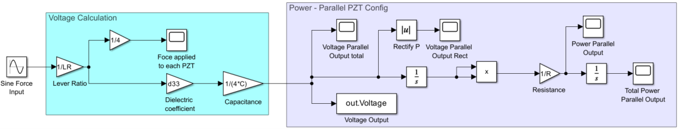
Before any physical build, I developed a MATLAB/Simulink model to simulate power generation under cyclic loading. The inputs were grounded in real vehicle data: load amplitudes were scaled from the kerb weights of production hybrids (Toyota Prius, RAV4, Honda CR-V), and the frequency range of 1.5 to 4Hz was taken from published data on sprung mass vertical motion in passenger vehicles.
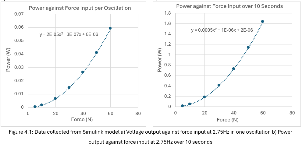
The main finding from the simulation was that power output scales quadratically with applied force, confirming the theoretical relationship P proportional to F squared. At 60N input, the model predicted roughly 0.06W per oscillation, and around 1.6W of total harvested energy over 10 seconds at that load. The frequency analysis also showed something worth noting: power per oscillation decreases as frequency increases, but total energy harvested over a fixed time period stays approximately constant, because a higher frequency means more cycles in that period. The two effects offset each other almost exactly.
 MATLAB simulation output
The model was intentionally idealised. It assumed no friction, no damping, no dielectric leakage, constant material properties, clean sinusoidal inputs, and linear force-to-voltage behaviour with no upper limit. These were acknowledged limitations, and several of them turned out to matter when physical testing began.
The Prototype: Four Iterations
The physical prototype went through four design iterations before reaching a form that was stable enough to test properly.
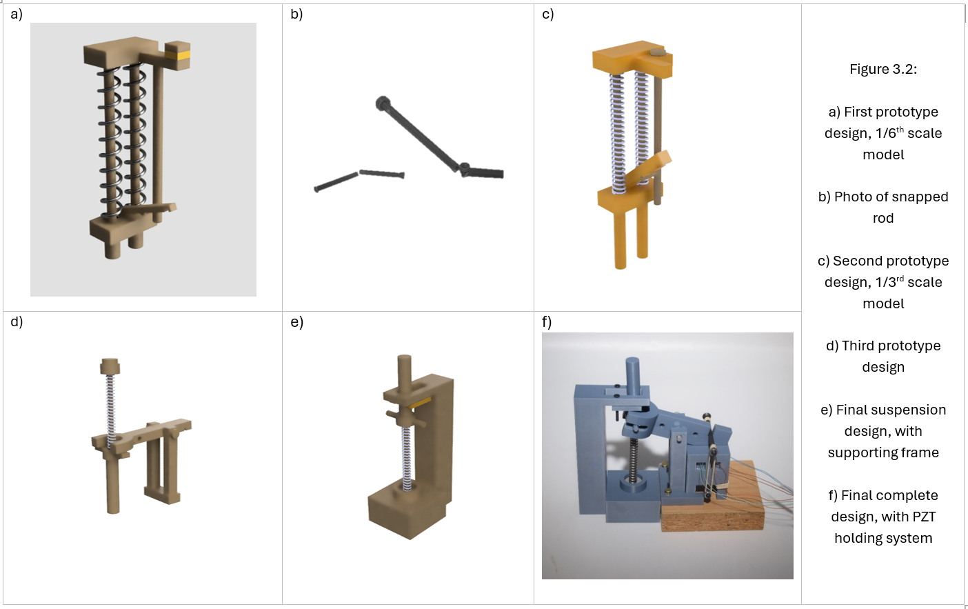
The first version was built at 1/6 scale to keep material costs down. It didn't make it through assembly: the slender rod holding the lever pivot fractured on the first load application. The geometry was sound in principle, but 3D printing inaccuracies are proportionally larger at smaller scales, and thin components under real applied force behaved very differently to how they appeared in the CAD model. The decision to scale up to 1/3 added cost and time, but it was clearly the right call.
The 1/3 scale version was structurally better, but introduced a new problem. The lever was mounted passively on a pivot and depended on system movement to return to position after each oscillation. Under dynamic loading, there was nothing keeping the lever connected to the suspension's protruding arms on the upward stroke, so it disconnected mid-cycle. The fix was to redesign the lever so it wrapped around both sides of the arm with a central pin locking the pivot in place, but the resulting support frame became unstable under load because of its narrow base, and the whole system orientation turned out to be incompatible with the tensile tester that would be used for testing.
Inverting the system to fit the test equipment required a structural rethink, and that ended up improving the design significantly. Earlier iterations had been near-monolithic assemblies, which made adjustments slow and difficult. The final design used slotted and bolted connections throughout, a wide lever base that interlocked with the PZT holder to eliminate tipping, a dedicated holder with individual slots for each of the four PZT discs, and wire routing holes to keep the electrical connections tidy. It was far easier to assemble, modify, and repair than anything that came before it.
 Prototype design iterations
One design decision worth explaining separately is the elastic band used as the force coupling between the lever and the PZT stack. The PZT elements cost £64.92 of a total project budget of £73.29, which is nearly 90% of the budget in a single component. Damaging one during testing would have been a serious problem, and there was real concern about applying force too quickly or unevenly across the elements. The elastic band provides progressive rather than sudden force application, acts as secondary damping, and if the system is overloaded, it snaps before the PZT is damaged. That was a deliberate design choice made partly out of financial necessity, but it also makes sense from a maintenance perspective in a production context: a replaceable elastic element failing before an expensive transducer means the cheaper part takes the damage.
Testing and Results
Testing was carried out on the H1KS 1kN benchtop tensile tester, with a Tektronix oscilloscope measuring voltage output and MATLAB processing the data.
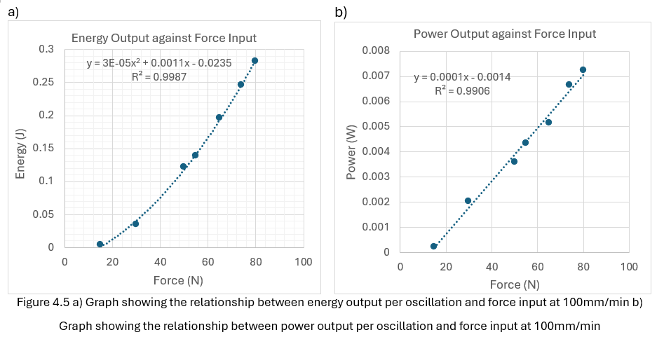
The most consistent finding was a strong linear relationship between applied force and voltage output, with an R² of 0.9713 across force levels from 15N to 80N at 100mm per minute. This is consistent with piezoelectric theory. The speed of force application turned out to have almost no effect: varying the loading rate from 30 to 100mm per minute at a fixed force of 50N produced near-constant voltage output, which confirmed that force magnitude is the primary driver of output, not the rate of change.
Above around 60N, the rated combined limit of four parallel elements at 15N each, the voltage output stopped increasing despite continued force application. The output saturated due to dipole domain alignment reaching its limit within the PZT material. This nonlinearity was not present in the Simulink model, which had assumed linear behaviour at all force levels. It was only discovered through physical testing, and it has significant implications for any scaling analysis.
 Experimental results
The gap between simulation and physical performance also showed up in the efficiency figures. The experimentally derived piezoelectric coefficient was 138.2 pC/N, compared to 285 pC/N for PZT-4 and 225 pC/N for PZT-8, around 50 to 60 percent lower than the reference values. The most likely contributing factors were that the TDK component's exact material composition is not disclosed and is probably optimised for mechanical durability rather than charge generation efficiency, the PLA structure absorbs some strain under load rather than transmitting it fully to the PZT elements, and the elastic band introduces a damping stage that was not accounted for in the model.
Extrapolating to full vehicle suspension loads of 400 to 900N per corner and using the experimentally derived energy-force relationship at 700N, gives an estimated output of around 169W per vehicle. In context, a plug-in hybrid in electric mode at 50km/h consumes roughly 208Wh/km, so 169W recovered continuously represents about 1.6% of total consumption. The contribution is modest, but it comes from energy that is being dissipated regardless of what the vehicle is doing and would otherwise be completely lost. The most practical application would be powering low-draw systems like cabin electronics, lighting, or auxiliary battery trickle charging, offsetting parasitic loads on the main battery rather than contributing to primary propulsion.
Reflections
Managing a project with no prescribed structure across seven months taught me more about planning and iteration than any module with a predefined brief would have. I used a Trello board from the start to break the project into stages and track deadlines, which made it easier to adapt when things needed revisiting without losing sight of what still had to be delivered. The things I would do differently are fairly clear in hindsight: conduct a more thorough and systematic comparison of transduction methods before committing to piezoelectric, design around the available test equipment from the beginning rather than adapting to it partway through, and build contingency time into the schedule from the outset rather than absorbing delays through reprioritisation under pressure.
One thing that did work well was purchasing a wider range of spring sizes in a single order early in the project, anticipating that design changes would require different spring specifications. When the scale-up from 1/6 to 1/3 happened, testing could continue without waiting on further procurement. Thinking proactively about what might change, and making decisions in advance to absorb that uncertainty, is something I've carried into projects since.
I was really grateful that this project received the IMechE Best Project Award and the Year 3 Head of School Award. These are awards that I am hugely proud of!
 IMechE Best Project Award and Year 3 Head of School Award
More Projects

Study LLM: A RAG-Based Academic Knowledge Base
A multi-user platform that ingests university course materials and answers questions grounded in the uploaded content, with citations back to the source. Full backend complete, frontend in progress.

Daily Stock Update: An Evening Portfolio Briefing
An n8n workflow that reads a personal stock portfolio from a Google Sheet, pulls live prices and 30-day history from Alpha Vantage, pairs the data with Tavily sentiment research, and emails a formatted report every evening at 21:30.